What is an Embedded System?
An
embedded system can be defined as a computing device that does a specific
focused job. Appliances such as the air-conditioner, VCD player, DVD player,
printer, fax machine, mobile phone etc. are examples of embedded systems. Each
of these appliances will have a processor and special hardware to meet the
specific requirement of the application along with the embedded software that
is executed by the processor for meeting that specific requirement. The
embedded software is also called “firm ware”. The desktop/laptop computer is a
general purpose computer. You can use it for a variety of applications such as
playing games, word processing, accounting, software development and so on. In
contrast, the software in the embedded systems is always fixed.
History:
In the
earliest years of computers in the 1940s, computers were sometimes dedicated to
a single task, but were too large to be considered "embedded". Over
time however, the concept of programmable controllers developed from a mix of
computer technology, solid state devices, and traditional electromechanical
sequences.
The
first recognizably modern embedded system was the Apollo Guidance Computer,
developed by Charles Stark Draper at the MIT Instrumentation Laboratory. At the
project's inception, the Apollo guidance computer was considered the riskiest
item in the Apollo project. The use of the then new monolithic integrated
circuits, to reduce the size and weight, increased this risk.
The
first mass-produced embedded system was the Autonetics D-17 guidance computer
for the Minuteman (missile), released in 1961. It was built from
transistorlogic and had a hard disk for main memory. When the Minuteman II went
into production in 1966, the D-17 was replaced with a new computer that was the
first high-volume use of integrated circuits. This program alone reduced prices
on quad nand gate ICs from $1000/each to $3/each, permitting their use in
commercial products.
Since
these early applications in the 1960s, embedded systems have come down in
price. There has also been an enormous rise in processing power and
functionality. For example the first microprocessor was the Intel 4004, which
found its way into calculators and other small systems, but required external
memory and support chips.
In 1978
National Engineering Manufacturers Association released the standard for a
programmable microcontroller. The definition was an almost any computer-based
controller. They included single board computers, numerical controllers, and
sequential controllers in order to perform event-based instructions.
By the
mid-1980s, many of the previously external system components had been
integrated into the same chip as the processor, resulting in integrated
circuits called microcontrollers, and widespread use of embedded systems became
feasible.
As the
cost of a microcontroller fell below $1, it became feasible to replace
expensive knob-based analog components such as potentiometers and variable
capacitors with digital electronics controlled by a small microcontroller with
up/down buttons or knobs. By the end of the 80s, embedded systems were the norm
rather than the exception for almost all electronics devices, a trend which has
continued since.
Embedded
systems are characterized by some special features listed below:
Ø Embedded systems do a very
specific task; they cannot be programmed to do different things. . Embedded
systems have very limited resources, particularly the memory. Generally, they
do not have secondary storage devices such as the C DROM or the floppy disk.
Embedded systems have to work against some deadlines. A specific job has to be
completed within a specific time. In some embedded systems, called real-time
systems, the deadlines are stringent. Missing a deadline may cause a
catastrophe-loss of life or damage to property. Embedded systems are
constrained for power. As many embedded systems operate through a battery, the
power consumption has to be very low.
Ø Embedded systems need to be
highly reliable. Once in a while, pressing ALT-CTRL-OEL is OK on your desktop,
but you cannot afford to reset your embedded system.
Ø Some embedded systems have to
operate in extreme environmental conditions such as very high temperatures and
humidity.
Ø Embedded systems that address the
consumer market (for exam-ple, electronic toys) are very cost-sensitive: Even a
reduction of $0.1 is lot of cost saving, because thousands or millions systems
may be sold.
Ø Unlike desktop computers in which
the hardware platform is dominated by Intel and the operating system is
dominated by Microsoft, there is a wide variety of processors and operating
systems for the embedded systems. So, choosing the right plat-form is the most
complex task.
APPLICATION AREAS
Nearly 99 per cent of the
processors manufactured end up in embedded systems. The embedded system market
is one of the highest growth areas as these systems are used in very market
segment- consumer electronics, office automation, industrial automation,
biomedical engineering, wireless communication, data communication,
telecommunications, transportation, military and so on.
Consumer
appliances: At
home we use a number of embedded systems which include digital camera, digital
diary, DVD player, electronic toys, microwave oven, remote controls for TV and
air-conditioner, VCO player, video game consoles, video recorders etc. Today’s
high-tech car has about 20 embedded systems for transmission control, engine
spark control, air-conditioning, navigation etc. Even wristwatches are now
becoming embedded systems. The palmtops are powerful embedded systems using
which we can carry out many general-purpose tasks such as playing games and
word processing.
Office
automation: The
office automation products using embedded systems are copying machine, fax
machine, key telephone, modem, printer, scanner etc. Industrial automation:
Today a lot of industries use embedded systems for process control. These
include pharmaceutical, cement, sugar, oil exploration, nuclear energy,
electricity generation and transmission. The embedded systems for industrial
use are designed to carry out specific tasks such as monitoring the
temperature, pressure, humidity, voltage, current etc., and then take
appropriate action based on the monitored levels to control other devices or to
send information to a centralized monitoring station. In hazardous industrial
environment, where human presence has to be avoided, robots are used, which are
programmed to do specific jobs. The robots are now becoming very powerful and
carry out many interesting and complicated tasks such as hardware assembly.
CATEGORIES
OF EMBEDDED SYSTEMS
Based on
functionality and performance requirements, embedded systems can be categorized
as:
• Stand-alone
embedded systems
• Real-time
systems
• Networked
information appliances
• Mobile
devices
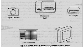
Stand
alone Embedded Systems:
As the
name implies, stand-alone systems work in stand-alone mode. They take inputs,
process them and produce the desired output. The input can be electrical
signals from transducers or commands from a human being such as the pressing of
a button. The output can be electrical signals to drive another system, an LED
display or LCD display for displaying of information to the users. Embedded
systems used in process co~1’rol, automobiles, consumer electronic items etc.
fall into this category. In a process control system, the inputs are from
sensors that convert a physical entity such as temperature or pressure into its
equivalent electrical signal. These electrical signals are processed by the
system and the appropriate electrical signals are produced using which an
action is taken such as opening a valve. A few embedded systems used at home
are shown in fig
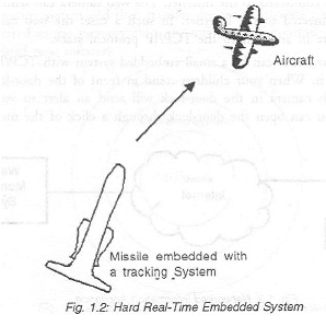
REAL TIME SYSTEMS
Embedded
systems in which some specific work has to be done in a specific time period
are called real-time systems. For example, consider a system that has to open a
valve within 30milliseconds when the humidity crosses a particular threshold.
If the valve is not opened within 30 milliseconds, a catastrophe may occur.
Such systems with strict deadlines are called hard real-time’ systems. In some
embedded systems, deadlines are imposed, but not adhering to them once in a
while may not lead to a catastrophe. For example, consider a DVD player.
Suppose, you give a command to the DVD player from remote control, and there is
a delay of a few milliseconds in executing that command. But, this delay won’t
lead to a serious implication. Such systems are called soft real-time systems.
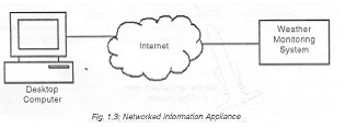
NETWORKED INFORMATION APPLIANCES
Embedded
systems that are provided with network interfaces and accessed by networks such
as Local Area Network or the Internet are called networked information
appliances. Such embedded systems are connected to a network, typically a
network running TCP/IP (Transmission Control Protocol! Internet Protocol)
protocol suite, such as the Internet or a company’s Intranet. These systems
have emerged in recent years These systems run the protocol TCP/IP stack and
get connected either through PPP or Ethernet to a network and communicate with
other nodes in the network. Here are some examples of such systems:
MOBILE DEVICES
Mobile
devices such as mobile phones, Personal Digital Assistants (PDAs), smart phones
etc. are a special category of embedded systems. Though the PDAs do many
general purpose tasks, they need to be designed just like the ‘conventional’
embedded systems. The limitations of –the mobile devices- memory constraints,
small size, lack of good user interfaces such as full-fledged keyboard and
display etc.-are same as those found in the embedded systems discussed above.
Hence, mobile devices are considered as embedded systems. However, the PDAs are
now capable of supporting general-purpose application software such as word
processors, games, etc.
User
interfaces
Embedded
systems range from no user interface at all - dedicated only to one task - to
full user interfaces similar to desktop operating systems in devices such as
PDAs.
Simple
systems
Simple
embedded devices use buttons, LEDs, and small character- or digit-only
displays, often with a simple menu system.
In
more complex systems
A full
graphical screen, with touch sensing or screen-edge buttons provides
flexibility while minimizing space used: the meaning of the buttons can change
with the screen, and selection involves the natural behavior of pointing at
what's desired. Handheld systems often have a screen with a "joystick
button" for a pointing device. The rise of the World Wide Web has given
embedded designers another quite different option: providing a web page
interface over a network connection. This avoids the cost of a sophisticated
display, yet provides complex input and display capabilities when needed, on
another computer. This is successful for remote, permanently installed
equipment. In particular, routers take advantage of this ability.
CPU
platform
Embedded
processors can be broken into two distinct categories: microprocessors
(μP) and micro controllers (μC). Micro controllers have built-in
peripherals on the chip, reducing size of the system. There are many different
CPU architectures used in embedded designs such as ARM, MIPS, Cold fire/68k,
PowerPC, x86, PIC, 8051, Atmel AVR, Renesas H8, SH, V850, FR-V, M32R, Z80, Z8,
etc. This in contrast to the desktop computer market, which is currently
limited to just a few competing architectures. PC/104 and PC/104+ are a
typical base for small, low-volume embedded and rugged system design. These
often use DOS, Linux, NetBSD, or an embedded real-time operating system such as
QNX or VxWorks. A common configuration for very-high-volume embedded systems
is the system on a chip (SoC), an application-specific integrated circuit
(ASIC), for which the CPU core was purchased and added as part of the chip
design. A related scheme is to use a field-programmable gate array (FPGA), and
program it with all the logic, including the CPU.
Peripherals
Embedded
Systems talk with the outside world via peripherals, such as:
Ø
Serial
Communication Interfaces (SCI): RS-232, RS-422, RS-485 etc
Ø
Synchronous
Serial Communication Interface: I2C, JTAG, SPI, SSC and ESSI
Ø
Universal
Serial Bus (USB)
Ø
Networks:
Controller Area Network, LonWorks, etc
Ø
Timers:
PLL(s), Capture/Compare and Time Processing Units
Ø
Discrete IO:
aka General Purpose Input Output (GPIO)
Tools
As for
other software, embedded system designers use compilers, assemblers, and
debuggers to develop embedded system software. However, they may also use some
more specific tools:
Ø
An in-circuit
emulator (ICE) is a hardware device that replaces or plugs into the
microprocessor, and provides facilities to quickly load and debug experimental
code in the system.
Ø
Utilities to
add a checksum or CRC to a program, so the embedded system can check if the
program is valid.
Ø
For systems
using digital signal processing, developers may use a math workbench such as
MathCAD or Mathematic to simulate the mathematics.
Ø
Custom
compilers and linkers may be used to improve optimization for the particular
hardware.
Ø
An embedded
system may have its own special language or design tool, or add enhancements to
an existing language.
Software
tools can come from several sources:
Ø
Software
companies that specialize in the embedded market
Ø
Ported from
the GNU software development tools
Ø
Sometimes,
development tools for a personal computer can be used if the embedded processor
is a close relative to a common PC processor
Debugging
Embedded
Debugging may be performed at different levels, depending on the facilities
available, ranging from assembly- or source-level debugging with an in-circuit
emulator or in-circuit debugger, to output from serial debug ports or
JTAG/Nexus interfaces, to an emulated environment running on a personal
computer.As the complexity of embedded systems grows, higher level tools and
operating systems are migrating into machinery where it makes sense. For
example, cell phones, personal digital assistants and other consumer computers
often need significant software that is purchased or provided by a person other
than the manufacturer of the electronics. In these systems, an open programming
environment such as Linux, NetBSD, OSGi or Embedded Java is required so that
the third-party software provider can sell to a large market.
Reliability
Embedded
systems often reside in machines that are expected to run continuously for
years without errors, and in some cases recover by themselves if an error
occurs. Therefore the software is usually developed and tested more carefully
than that for personal computers, and unreliable mechanical moving parts such
as disk drives, switches or buttons are avoided.Recovery from errors may be
achieved with techniques such as a watchdog timer that resets the computer
unless the software periodically notifies the watchdog.
Specific
reliability issues may include:
Ø
The system
cannot safely be shut down for repair, or it is too inaccessible to repair.
Solutions may involve subsystems with redundant spares that can be switched
over to, or software "limp modes" that provide partial function.
Examples include space systems, undersea cables, navigational beacons,
bore-hole systems, and automobiles.
Ø
The system
must be kept running for safety reasons. "Limp modes" are less
tolerable. Often backups are selected by an operator. Examples include aircraft
navigation, reactor control systems, safety-critical chemical factory controls,
train signals, engines on single-engine aircraft.
Ø
The system
will lose large amounts of money when shut down: Telephone switches, factory
controls, bridge and elevator controls, funds transfer and market making,
automated sales and service.
High
vs Low Volume
For high
volume systems such as portable music players or mobile phones, minimizing cost
is usually the primary design consideration. Engineers typically select
hardware that is just “good enough” to implement the necessary functions. For
low-volume or prototype embedded systems, general purpose computers may be
adapted by limiting the programs or by replacing the operating system with a
real-time operating system.
Embedded
software architectures
There
are several different types of software architecture in common use.
Simple
control loop
In this
design, the software simply has a loop. The loop calls subroutines, each of
which manages a part of the hardware or software.
Interrupt
controlled system
Some
embedded systems are predominantly interrupt controlled. This means that tasks
performed by the system are triggered by different kinds of events. An
interrupt could be generated for example by a timer in a predefined frequency,
or by a serial port controller receiving a byte. These kinds of systems are
used if event handlers need low latency and the event handlers are short and
simple. Usually these kinds of systems run a simple task in a main loop also,
but this task is not very sensitive to unexpected delays. The tasks performed
in the interrupt handlers should be kept short to keep the interrupt latency to
a minimum. Some times longer tasks are added to a queue structure in the
interrupt handler to be processed in the main loop later. This method brings
the system close to a multitasking kernel with discrete processes. Cooperative
multitasking
A
no preemptive multitasking system is very similar to the simple control loop
scheme, except that the loop is hidden in an API. The programmer defines a
series of tasks, and each task gets its own environment to "run" in.
Then, when a task is idle, it calls an idle routine (usually called
"pause", "wait", "yield", etc.). The advantages
and disadvantages are very similar to the control loop, except that adding new
software is easier, by simply writing a new task, or adding to the
queue-interpreter.
Preemptive
multitasking
In this
type of system, a low-level piece of code switches between tasks based on a
timer. This is the level at which the system is generally considered to have an
"operating system", and introduces all the complexities of managing
multiple tasks running seemingly at the same time. Any piece of task code can
damage the data of another task; they must be precisely separated. Access to
shared data must be controlled by some synchronization strategy, such as message
queues, semaphores or a non-blocking synchronization scheme. Because of these
complexities, it is common for organizations to buy a real-time operating
system, allowing the application programmers to concentrate on device
functionality rather than operating system services.